Camera moduleLink
Size: 148mm x 143mm x 63mm
Weight: 560gr
CMOS sensor: 12.3 mp, Sony IMX477 sensor.
Optics: Support for C- and CS-mount lenses.
Networking: Wi-Fi 2.4GHz 802.11 b/g/n
Interfaces: UART Serial, I2C, SWD.
Both the Cablebot and the Scanner require a reliable camera module, although the usage in both cases is slightly different For the Scanner, the camera is positioned at a given angle. The movement from angle position to the next is relatively infrequent and slow. For the Cablebot, the camera must adjust in real-time for swinging movements of the system.
Controller boardLink
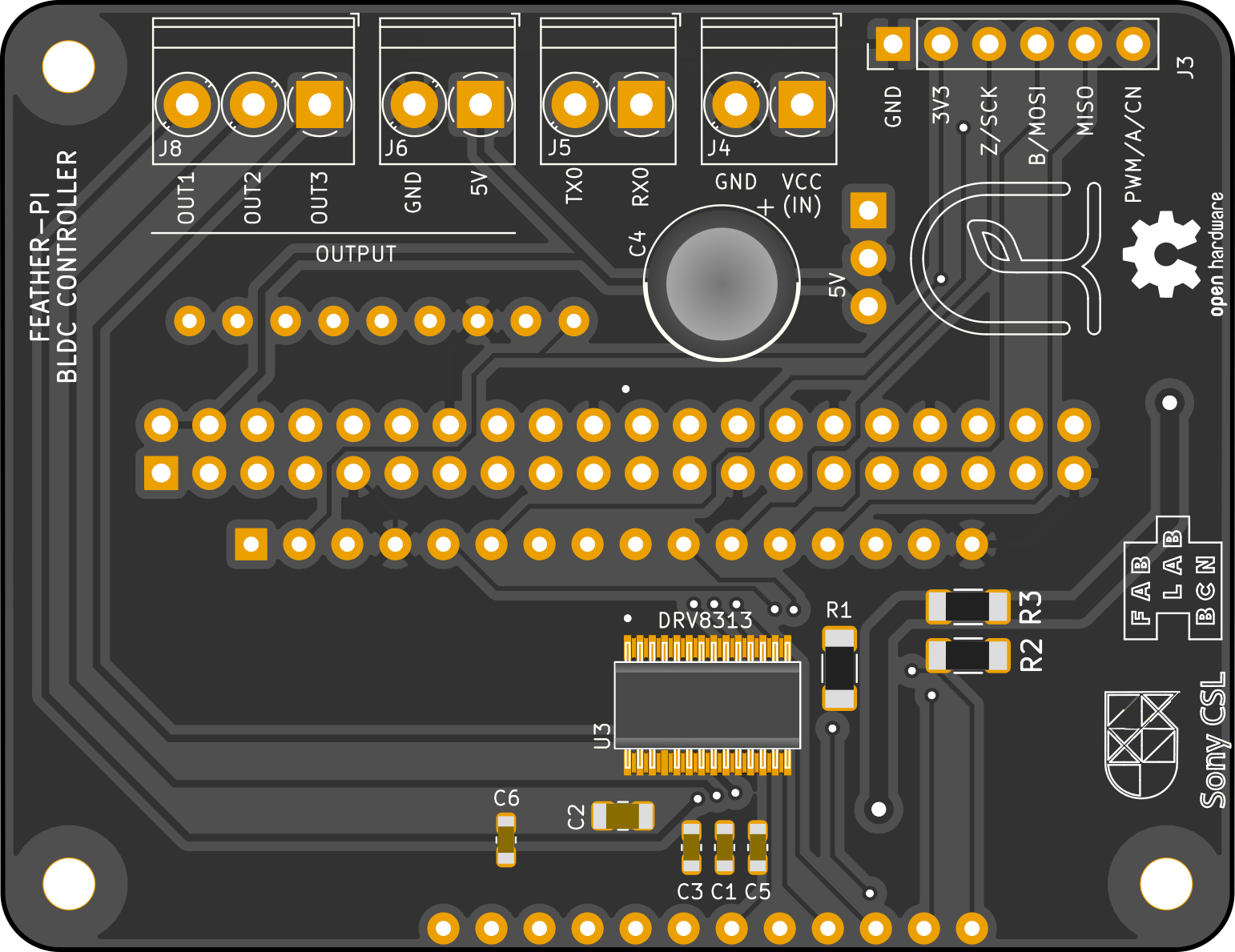
We decided to use a brushless motor, as is the custom in camera mount systems. We designed a controller board that exploits the functions offered by the TI DRV8313 chip. The DRV8313 requires as an input three Pulse Width Modulation signals (PWM) that encode the phase of each of the three voltages applied to the solenoids of the brushless motor.
The control software is integrated into the code for the Romi Rover: https://github.com/romi/libromi/tree/ci_dev/firmware/BLDC The design files can be found at https://github.com/romi/bldc_featherwing
MicrocontrollerLink
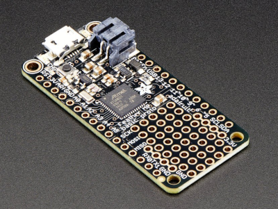
The PWMs signals should be of a high frequency, as to avoid any ripples in the signal, and should be closely synchronised. We therefore opted for a Cortex M0 microcontroller instead of the more common AVR microcontrollers found on the Arduino Uno, for example. Concretely, we are using the Adafruit Feather M0 Basic, but the code should run on any Arduino -compatible SAMD21 microcontroller board.
Motor and encoderLink
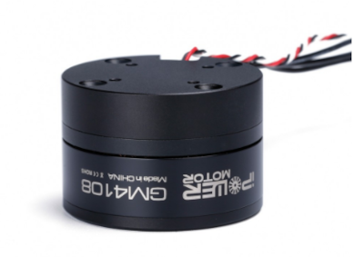
To estimate the angular position of the motor we use a HAL-based encoder. We are using standard components that are sold for the drone market. In particular, we are using the iPower Motor GM4108H-120T Gimbal Motor with AS5048A Encoder and slip ring from iFlight-rc.com.
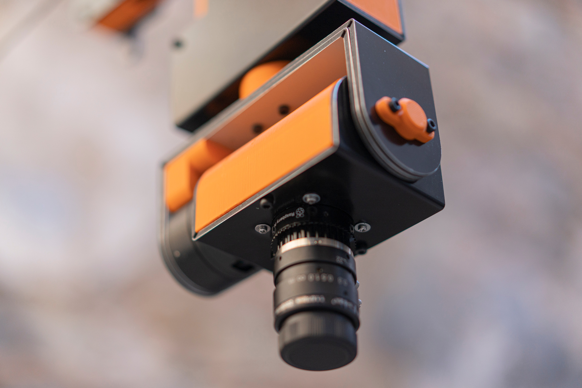
CameraLink
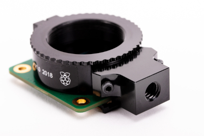
We use the recent Raspberry Pi High Quality Camera Module. The module is connected to the Raspberry Pi Zero W single-board computer. The camera module has a CS mount that allows us to change the lens.
WiringLink
We had recurring problems with the cabling of the cameras in our previous solutions. The micro USB connectors were not reliable enough and often lost contact. The transmission of the power and the communication over a long USB cable often failed (power drop, broken serial link). We therefore choose to bring a 12V cable to the camera, connect it over a sturdy plug, and include a DC-DC converter inside the camera. Also, we use the Wi-Fi functionality offered by the Raspberry Pi Zero W to send commands and download the images.
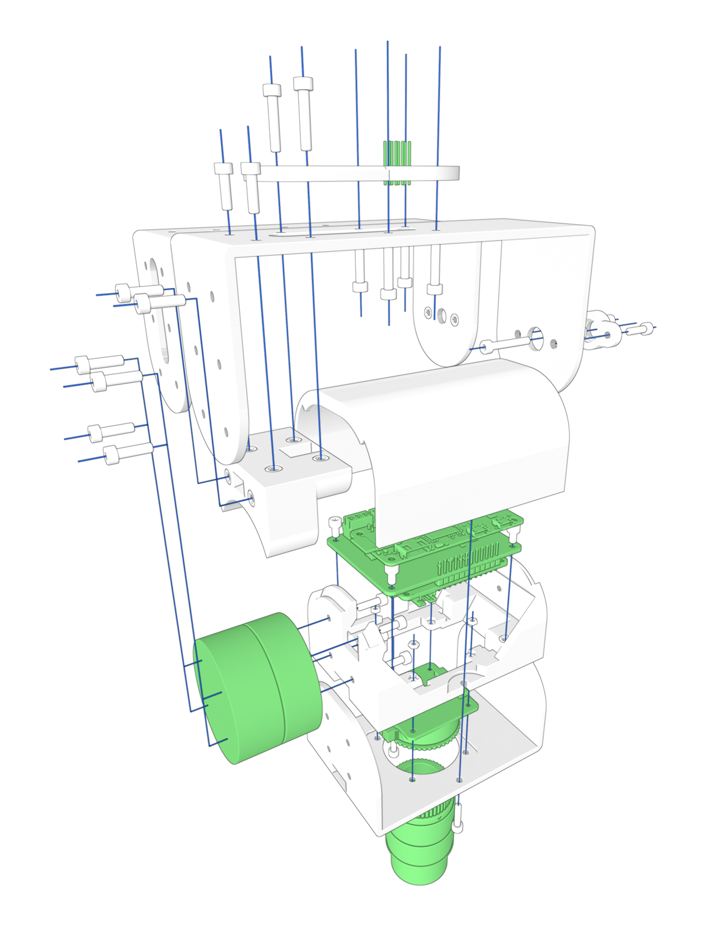
HousingLink
A housing was designed that follows the same production principles used in other cablebot components.