Calibrate the cameraLink
Some cameras introduce significant distortion to images. The two major kinds of distortion are radial distortion and tangential distortion.
With radial distortion, straight lines appear curved while with tangential distortion some objects of the image may appear closer than they are in reality.
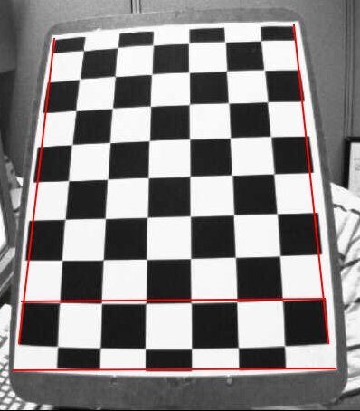
Illustration of an image captured with radial distortion as shown by the straight red lines added on top the picture afterward.
Source: OpenCV Python tutorial on camera calibration.
ObjectiveLink
Correcting these "aberrations" prior to image processing can be a good idea to improve quality and accuracy of the reconstructed 3D scenes by structure from motion algorithms.
In this tutorial, you will learn how to estimate the intrinsic camera parameters to calibrate image acquisition for downstream analysis and how to re-use it for a reconstruction pipeline, provided that the set-up is the same (same camera, optics, image size...).
PrerequisiteLink
-
Install the
plant-imagerROMI library required to perform image acquisitions together with the Plant Imager hardware. -
Install the
plant-3d-visionROMI library required to perform intrinsic calibration. -
Set up a ROMI
plantdblocal database or quickly create it (under/data/ROMI/DB) with the following commands:export ROMI_DB=/data/ROMI/DB mkdir $ROMI_DB touch $ROMI_DB/romidb
Step-by-step tutorialLink
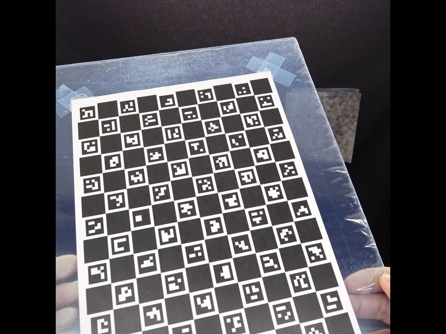
1. Make a ChArUco board and print itLink
A ChArUco board is the combination of a chess board and of ArUco markers.
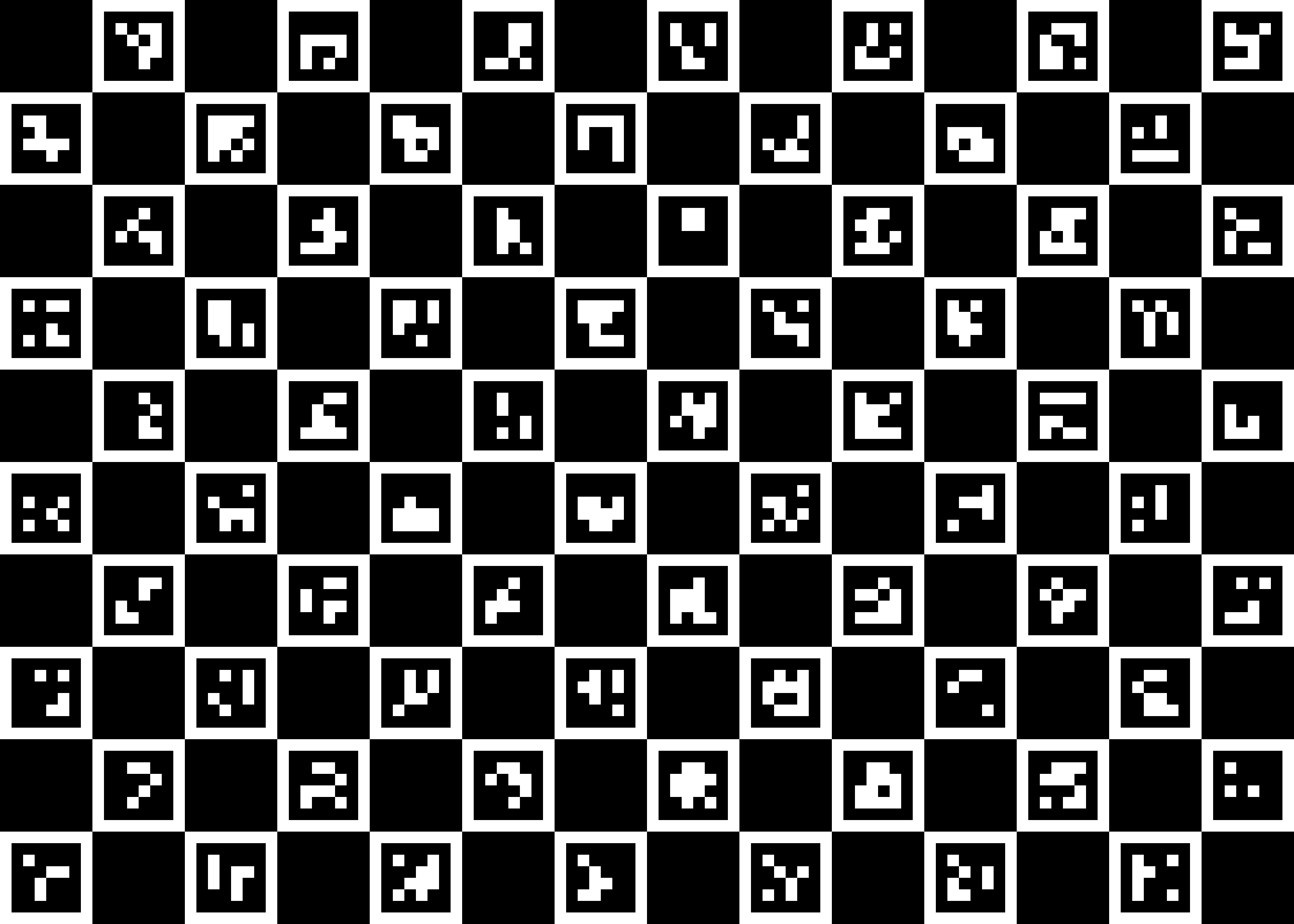
The previous figure shows the default board that we will use in this tutorial.
To create it, you have to run the create_charuco_board CLI as follows:
create_charuco_board plant-3d-vision/configs/intrinsic_calibration.toml
charuco_board.png in the current working directory.
We strongly advise to use the same TOML configuration file with create_charuco_board & romi_run_task commands to avoid inadvertently changing parameter values.
Also, you will later need it for the estimation of the intrinsic camera parameters.
An example of intrinsic_calibration.toml configuration file is:
[CreateCharucoBoard]
n_squares_x = "14"  # Number of chessboard squares in X direction.
n_squares_y = "10"  # Number of chessboard squares in Y direction.
square_length = "2."  # Length of square side, in cm
marker_length = "1.5"  # Length of marker side, in cm
aruco_pattern = "DICT_4X4_1000"  # 'DICT_4X4_50', 'DICT_4X4_100', 'DICT_4X4_250', 'DICT_4X4_1000'

[DetectCharuco]
upstream_task = "ImagesFilesetExists"
board_fileset = "CreateCharucoBoard"
min_n_corners = "20"  # Minimum number of detected corners to export them

[IntrinsicCalibration]
upstream_task = "DetectCharuco"
board_fileset = "CreateCharucoBoard"
You may now print the ChArUco board image. Pay attention to use a software (like GIMP) that allows you to set the actual size of the image you want to print. With the previous configuration it should be:
- width :
n_squares_x * square_length = 14 * 2. = 28cm - height :
n_squares_y * square_length = 10 * 2. = 20cm
Finally, tape it flat onto something solid in order to avoid deformation of the printed pattern!
2. Scan the ChArUco boardLink
To scan your newly printed ChArUco board, use the IntrinsicCalibrationScan task from plant_imager:
romi_run_task IntrinsicCalibrationScan $ROMI_DB/intrinsic_calib_1 --config plant-3d-vision/configs/scan.toml
The camera should move to the center front of the plant imager where you will hold your pattern and take 20 pictures (according to the previous configuration).
Try to take pictures of the board in different positions.
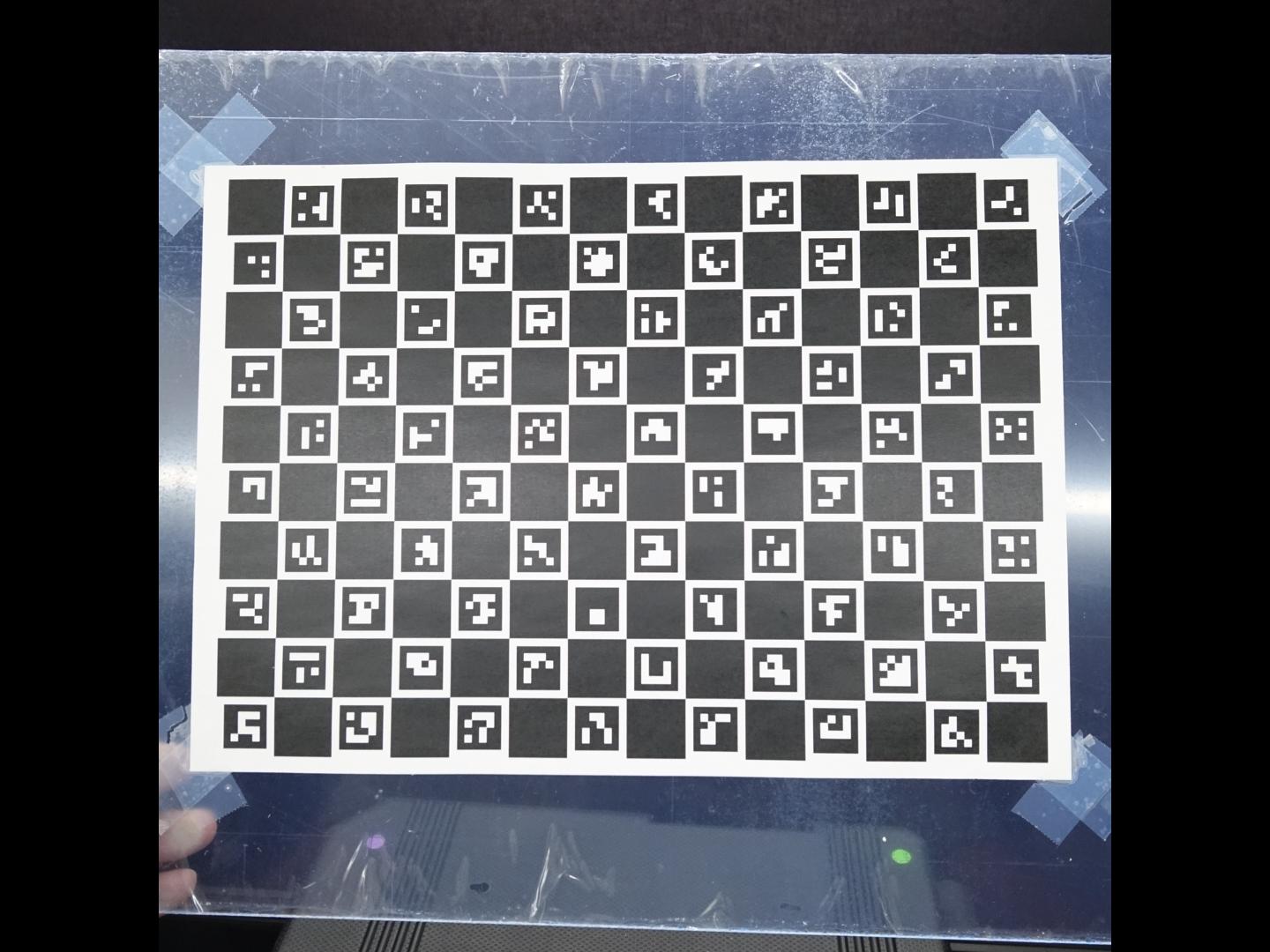
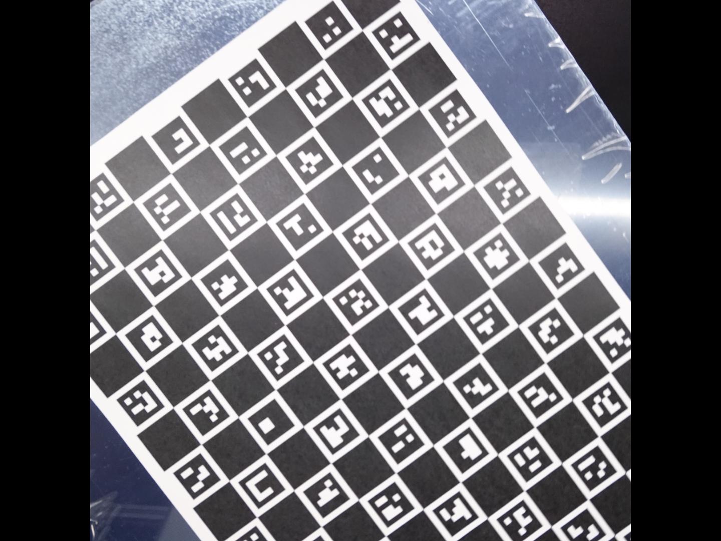
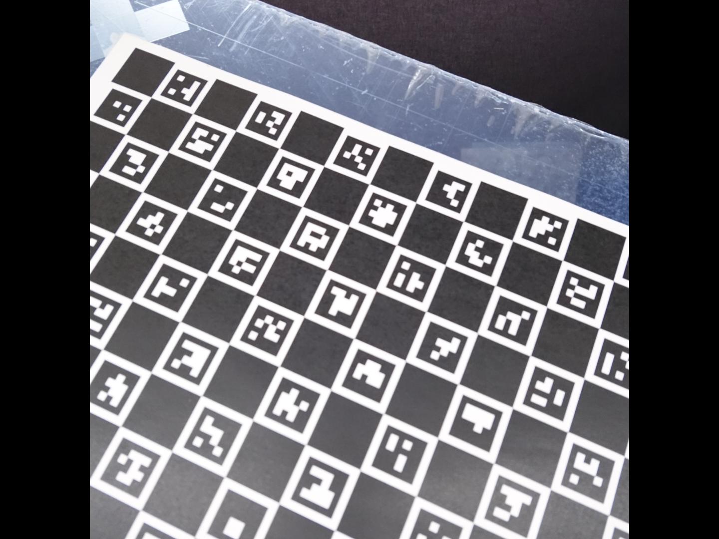
As illustrated by the previous image examples, it is not required to have the whole board in the picture, the ArUco markers will be used to detect the occluded sections!
An example for the scan.toml configuration file is:
[IntrinsicCalibrationScan]
n_poses = 20  # Number of acquisition of the printed ChArUco board
offset = 5

[CalibrationScan]
n_points_line = 11
offset = 5

[ScanPath]
class_name = "Circle"

[ScanPath.kwargs]
center_x = 375
center_y = 375
z = 90
tilt = 0
radius = 300
n_points = 36

[Scan.scanner.camera]
module = "plantimager.sony"  # RX-0 camera

[Scan.scanner.gimbal]
module = "plantimager.blgimbal"  # plant imager hardware v2

[Scan.scanner.cnc]
module = "plantimager.grbl"  # plant imager hardware v2

[Scan.metadata.object]
species = "none"
seed_stock = "none"
plant_id = "test"
growth_environment = "none"
growth_conditions = "None"
treatment = "none"
DAG = 0
sample = "test_sample"
experiment_id = "None"
dataset_id = "test"

[Scan.metadata.hardware]
frame = "30profile v2"
X_motor = "X-Carve NEMA23"
Y_motor = "X-Carve NEMA23"
Z_motor = "X-Carve NEMA23"
pan_motor = "iPower Motor GM4108H-120T Brushless Gimbal Motor"
tilt_motor = "None"
sensor = "Sony RX-0"

[Scan.metadata.workspace]
x = [ 100, 500,]
y = [ 100, 500,]
z = [ -300, 100,]

[Scan.scanner.camera.kwargs]
device_ip = "192.168.122.1"
api_port = "10000"
postview = true
use_flashair = false
rotation = 270

[Scan.scanner.gimbal.kwargs]
port = "/dev/ttyACM1"
has_tilt = false
zero_pan = 0
invert_rotation = true

[Scan.scanner.cnc.kwargs]
port = "/dev/ttyACM0"
baud_rate = 115200
homing = true
3. Performs the camera parameters estimationLink
You may now estimate the camera parameters, for a given camera model with:
romi_run_task IntrinsicCalibration $ROMI_DB/intrinsic_calib_1 --config plant-3d-vision/configs/intrinsic_calibration.toml
camera_model.json inside the $ROMI_DB/intrinsic_calib_1/camera_model folder.
An example of a camera_model.json file is:
{
    "model": "OPENCV",
    "RMS_error": 0.3484289537533634,
    "camera_matrix": [
        [
            1201.7588127324675,
            0.0,
            702.5429671940506
        ],
        [
            0.0,
            1199.117692017527,
            536.7266695161917
        ],
        [
            0.0,
            0.0,
            1.0
        ]
    ],
    "distortion": [
        0.021462456820485233,
        -0.04707700665017203,
        -0.00014475851274869323,
        -0.0011459776173976073,
        0.0
    ],
    "height": 1440,
    "width": 1080
}
Important
Do not hesitate to make several independent attempts at camera calibration, like 3 to 5, and choose the one with the lowest overall RMS error. Obviously, independent here means that you should perform multiple scans of the board and camera parameters estimation.