Hardware setup and instructionsLink
Network overviewLink
The general network design of the ROMI Plant Imager is as the following:
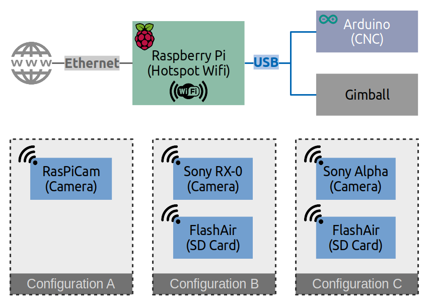
The raspberry pi controls the movements of the camera thanks to the CNC (for the x,y,z coordinates) and the Gimbal (pan and tilt).
Both of them are connected to the pi by USB cables.
For the camera, several configurations exists. It is possible to retrieve the photos either by Wi-Fi (might lead to a lower resolution) or directly via a micro USB.
Hardware configuration filesLink
To gather configuration information on the hardware during an acquisition with the plant imager we use toml files.
For example, saving the following lines in a config.toml:
[ScanPath]
class_name = "Circle" # Circle, Line, Cylinder

[ScanPath.kwargs]
center_x = 375
center_y = 375
z = 80
tilt = 0
radius = 300
n_points = 60

[Scan.scanner.cnc]
module = "plantimager.grbl"

[Scan.scanner.cnc.kwargs]
homing = true
port = "/dev/ttyACM0"

[Scan.scanner.gimbal]
module = "plantimager.blgimbal"

[Scan.scanner.gimbal.kwargs]
port = "/dev/ttyACM1"
has_tilt = false
zero_pan = 0
invert_rotation = true

[Scan.scanner.camera]
module = "plantimager.sony"

[Scan.scanner.camera.kwargs]
device_ip = "192.168.122.1"
api_port = "10000"
postview = true
use_flashair = false
rotation = 270

[Scan.metadata.object]
species = "chenopodium album"
seed_stock = "Col-0"
plant_id = "3dt_chenoA"
growth_environment = "Lyon-indoor"
growth_conditions = "SD+LD"
treatment = "None"
DAG = 40
sample = "main_stem"
experiment_id = "3dt_2021-01"
dataset_id = "3dt"

[Scan.metadata.hardware]
frame = "30profile v1"
X_motor = "X-Carve NEMA23"
Y_motor = "X-Carve NEMA23"
Z_motor = "X-Carve NEMA23"
pan_motor = "iPower Motor GM4108H-120T Brushless Gimbal Motor"
tilt_motor = "None"
sensor = "RX0"

[Scan.metadata.workspace]
x = [200, 600, ]
y = [200, 600, ]
z = [-100, 300, ]
Some arguments in this example have default values and for others (commented "mandatory" in the following description) it has to be specified in the configuration file.
Here, a more detailed explanation with a full default parameters list:
- The acquisition path:
[ScanPath] # mandatory
class_name = "Circle"
class_name defines the type of path the robotic arm will follow.
In this case it will be a circle, the other possibilities are commented next to the variable in the example above.
[ScanPath.kwargs] # mandatory
center_x = 375
center_y = 375
z = 80
tilt = 0
radius = 300
n_points = 60
The kwargs related to the path are in this section.
The arm will perform a circle of 300 around the point (375, 375) with a fixed z (80) and a tilt of 0°.
The angle between each pose will be 5° because the n_points is 60 on a 360° circle.
The center_x, center_y, z and radius parameters are expressed in mm and are related to the axis of the CNC.
To have an idea of valid values for those it's possible to get the limits of the CNC axis with steps described in the cnc calibration description.
- Needed parameters for connection between hardware components (CNC, Gimbal and camera) and software:
[Scan.scanner.cnc] # mandatory
module = "plantimager.grbl"
Here for example for the CNC you will have to inform about the python module required to connect to the hardware.
It will depend on the type of the device.
[Scan.scanner.cnc.kwargs]
homing = true
port = "/dev/ttyUSB0"
baud_rate = 115200
x_lims = None
y_lims = None
z_lims = None
safe_start = True
invert_x = true
invert_y = true
invert_z = true
The arguments all have default values here, but you might need to change the port (check with dmesg -w).
[Scan.scanner.gimbal] # mandatory
module = "plantimager.blgimbal"

[Scan.scanner.gimbal.kwargs]
port = "/dev/ttyUSB0"
has_tilt = True
steps_per_turn = 360
zero_pan = 0
zero_tilt = 0
invert_rotation = False
Similarly, for the Gimbal, again with default arguments that could be changed depending on your setup
[Scan.scanner.camera] # mandatory
module = "plantimager.sony" # or plantimager.gp2

[Scan.scanner.camera.kwargs]
device_ip = "192.168.122.1" # mandatory
api_port = "10000" # mandatory
timeout: time_s = 10
postview = false
use_adb = false
use_flashair = false
flashair_host = None
camera_params = None
rotation = 0
Finally, the camera (in this case the SONY RX0 communicating via Wi-Fi) with more specific arguments that will depend on the type of sensor used. A more precise documentation on several cameras and their associated parameters can be found here
-
Object metadata:
In principle, you can put any information that appear important as part of an experiment but to have a guideline of relevant parameters in the context of phenotyping you might want to check the biological metadata documentation -
Hardware metadata:
Again here, some guidelines for this section can be found in the hardware metadata description.
[Scan.metadata.workspace] # mandatory
x = [200, 600, ]
y = [200, 600, ]
z = [-100, 300, ]
Concerning the workspace, it is not properly required for the scan to perform but if a reconstruction is to be made it will be needed. As for the path, appropriate coordinates can be collected from information contained in the cnc calibration.
To load the config file in python:
>> > import toml
>> > conf = toml.load(open('config.toml'))
>> > print(conf)
{'Scan': {'scanner': {'camera_firmware': 'sony_wifi', 'cnc_firmware': 'grbl-v1.1', 'gimbal_firmware': 'blgimbal'}}}
>> > print(conf["Scan"]["scanner"]["camera_firmware"])
"sony_wifi"
PiZero camera rovercamLink
WORK IN PROGRESS!!!!!
Configuring the access point host software (hostapd)Link
Source: Raspberry Foundation website.
1. General setupLink
Switch over to systemd-networkd:
# remove classic networking
sudo apt --autoremove purge ifupdown dhcpcd5 isc-dhcp-client isc-dhcp-common
rm -r /etc/network /etc/dhcp

# enable systemd-networkd
systemctl enable systemd-networkd.service

# setup systemd-resolved
systemctl enable systemd-resolved.service
apt --autoremove purge avahi-daemon
apt install libnss-resolve
ln -sf /run/systemd/resolve/stub-resolv.conf /etc/resolv.conf
2. Configure wpa_supplicant as access pointLink
To configure wpa_supplicant as access point create this file with your settings for country=, ssid=, psk= and maybe frequency=.
You can just copy and paste this in one block to your command line beginning with cat and including both EOF (delimiter EOF will not get part of the file):
cat > /etc/wpa_supplicant/wpa_supplicant-wlan0.conf <<EOF
country=DE
ctrl_interface=DIR=/var/run/wpa_supplicant GROUP=netdev
update_config=1

network={
    ssid="RPiNet"
    mode=2
    frequency=2437
    #key_mgmt=NONE   # uncomment this for an open hotspot
    # delete next 3 lines if key_mgmt=NONE
    key_mgmt=WPA-PSK
    proto=RSN WPA
    psk="password"
}
EOF
chmod 600 /etc/wpa_supplicant/wpa_supplicant-wlan0.conf
systemctl disable wpa_supplicant.service
systemctl enable wpa_supplicant@wlan0.service
Setting up a stand alone access pointLink
Example for this setup:
                 wifi
mobile-phone <~.~.~.~.~> (wlan0)RPi(eth0)
            \             /
           (dhcp)   192.168.4.1
wlan0.
We only have the access point. There is no ethernet device configured.
cat > /etc/systemd/network/08-wlan0.network <<EOF
[Match]
Name=wlan0
[Network]
Address=192.168.4.1/24
MulticastDNS=yes
DHCPServer=yes
EOF
TroubleshootingLink
Serial access deniedLink
Look here if you can not communicate with the scanner using usb.