Wiring of the CNC electronicsLink
X-Controller assemblyLink
If you ordered the X-Controller, follow the official assembly instructions here.
Note
This is what we used in our second and third version of the phenotyping station hardware.
Warning
We replaced the default Grbl firmware by Oquam, our own implementation. See here for the instructions on how to flash this firmware to the X-Controller.
gShield assemblyLink
If you have the recent version, follow the official wiring instructions here.
Here is link to the post 2015 version of the "wiring" instructions.
Here is link to the post 2015 version of the "electronic assembly" instructions.
Note
This is what we used in our first version of the phenotyping station hardware.
BOMLink
If you are familiar with the Arduino world, the electronic is pretty straightforward:
- Arduino UNO (official buy here)
- Synthetos gShield (buy here)
- Power converter 220V ac. - 24V dc. (buy @Farnell)
- Emergency stop button (buy @Farnell)
Optional:
- 24V fan
- 220V power cord
Note
Before 2017 X-Carve shipped 400W power units, now they use a 320W unit. The link is for a 350W unit.
Wiring instructionsLink
Wire the Stepper Cable to the gShieldLink
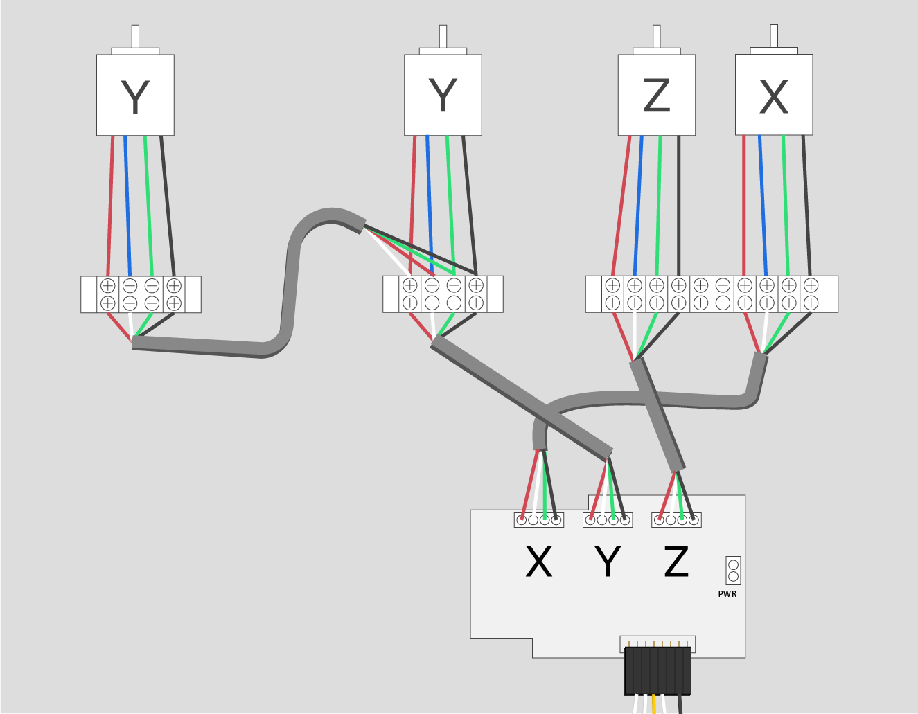
Once you’ve determined which stepper cable belongs to which axis, you can wire them into the gShield. First loosen all the screws on the gShield (they will jump a thread when they are fully loose, but they won’t come out of the terminal blocks.)
The gShield is marked "X," "Y," and "Z". Wire the stepper cable according to the markings on the shield and order your wires (from left to right) black, green, white, red.

Check out this diagram for clarification.
Mount the gShieldLink
Now push the gShield onto the Arduino. There are pins on the gShield that go into the headers of the Arduino.

24V Fan mount (optional)Link
If you want, you can add a 24V fan to cool the shield. Uses the 24V pins on the gShield as shown in the picture below:

Loosen the screws in the power terminal of the gShield and insert the red twisted pair into Vmot and the black twisted pair into GND.
Connect Limit Switches to gShieldLink
Crimp the white ends of each limit switch wire pair. The order of the white wires from left to right is X, Y, Z. The first, sixth, and eighth slots are left EMPTY.

Pin mapping:
D9: x-limit (red)D10: y-limit (red)D12: z-limit (red)GND: ground (all 3)
Power the gShieldLink
Loosen the screws in the power terminal of the gShield and insert the red twisted pair into Vmot and the black twisted pair into GND.
This is similar to the optional 24V fan.
Note
This will also power the Arduino.