Control electronicsLink
The entire motion system is controlled by a low-cost and low-power microcontroller (Microchip SAMD21) that interfaces with the camera module. The much powerful computer in the camera module runs the main logics and communication subsystem based on the software and hardware stack used in the Rover, ensuring modularity and scalability. As both the camera module and the Rover run the Raspberry PI ARM based Linux architecture our software stack is portable across each one of the robots. Those ensuring the Rover and the carrier use the same remote management interfaces. Following that approach the carrier can be managed using the same standard RC remote controller for on-site maintenance operations.
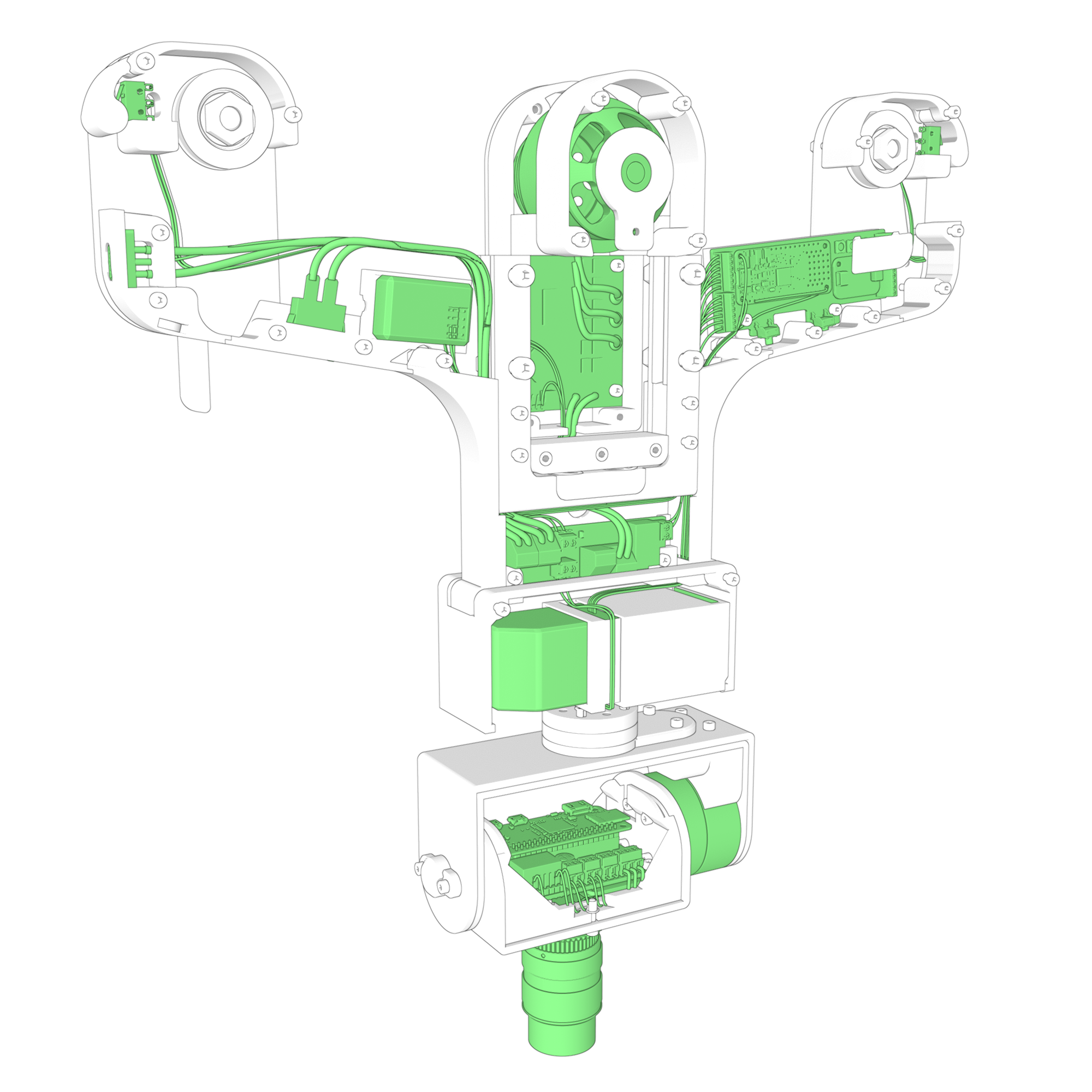
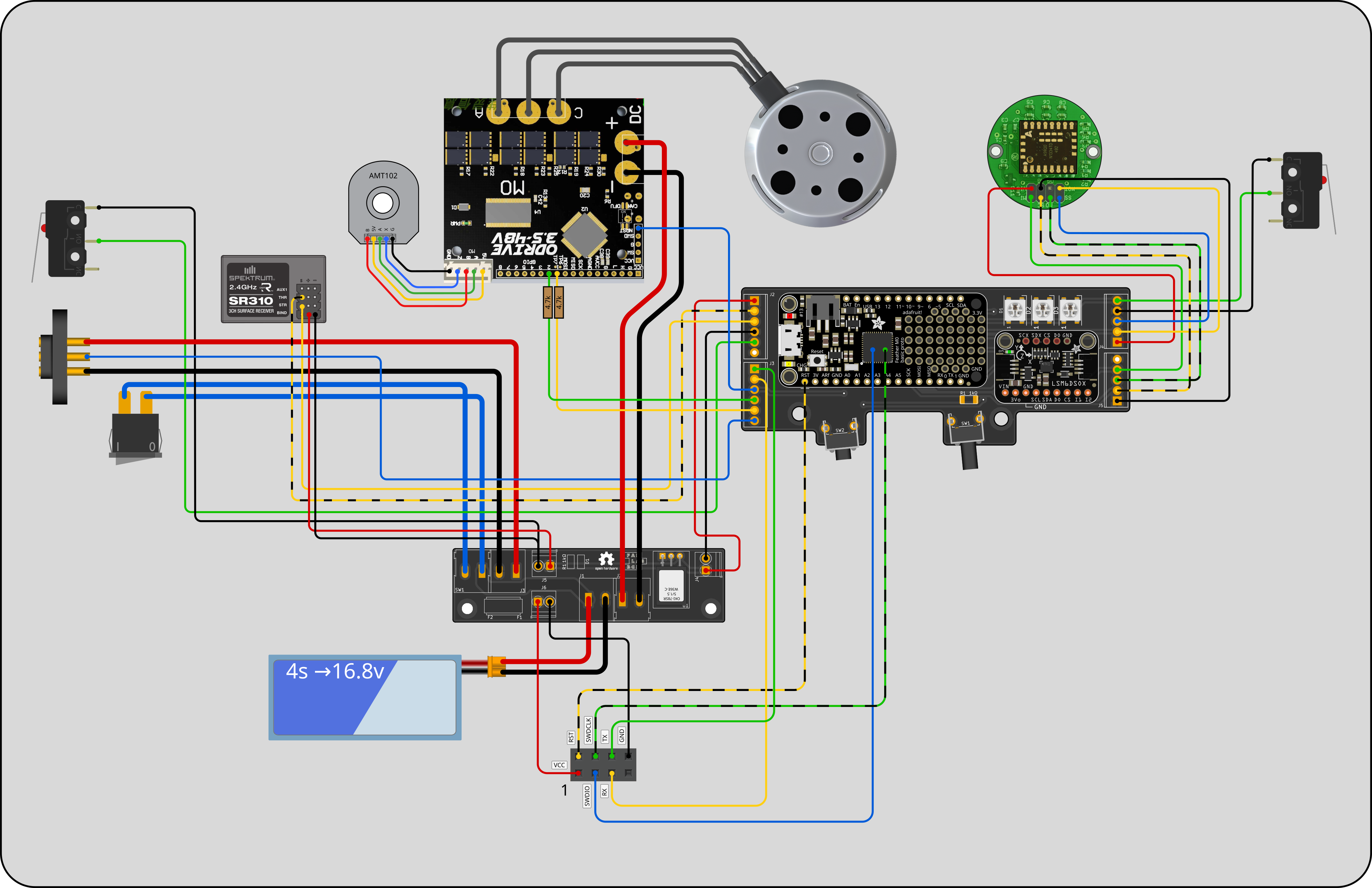
The Carrier module electronics is composed by three main PCB's: the control PCB that holds the man microcontroller on charge of the navigation, the Odrvie motor driver and the power distribution PCB.
Control PCBLink
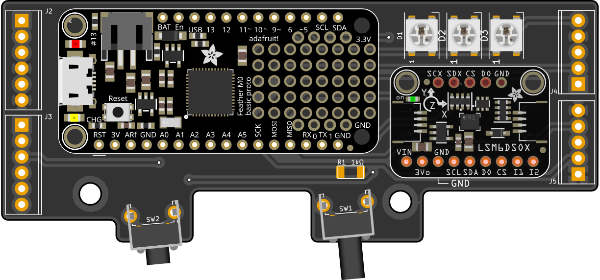
The navigation control is managed by any Arduino SAMD21 compatible board. This board will receive direct instructions via RC control or commands through the Serial port sent by the Raspberry pi in the Camera Module.
InputsLink
- Two endstops (2 interrupts)
- Position encoder (SPI)
- Motor encoder (1 interrupt)
- Battery voltage (from voltage dividerconnected to batt)
- RF speed channel (1 interrupts) we have a second channel with no use for now.
- USB or TX/RX only Serial port (level converter?).
- IMU (I2C)
- Charger connected input (1 interrupt)
- User button (1 interrupt)
OutputsLink
- Motor control (PWM)
- User led (Addressable RGB)
Feather PinoutLink
| Feather M0 Pin | Function | Int | ||
|---|---|---|---|---|
| 0 - RX (Serial1) (yellow) | PA11 | Odrive Serial GPIO1 → TX | SERCOM0.3 | |
| 1 - TX (Serial1) (green) | PA10 | Odrive Serial GPIO2 → RX | SERCOM0.2 | |
| 5 | PA15 | Addressable Led → DIN | ||
| 6 | PA20 | Endstop Front or right (was Back ¹) | 🟢 | |
| 9 | PA07 | Endstop Back or left (was Front ¹) | 🟢 | |
| 10 - TX0 (green) | PA18 | Camera Module → RX | SERCOM1.2 | |
| 11 | PA16 | RC → STR (Optional Gimbal control) | 🟢 | |
| 12 - RX0 (yellow) | PA19 | Camera Module → TX | SERCOM1.3 | |
| 13 | PA17 | RC Throttle → THR | 🟢 | |
| 15 - A1 | PB08 | Odrive Reset nRST (in J2) | ||
| 16 - A2 | PB09 | User Button | 🟢 | |
| 17 - A3 | PA04 | Charging station home int | 🟢 | |
| 18 - A4 | PA05 | ADNS → MOT | ||
| 19 - A5 | PB02 | ADNS → SS | ||
| 20 - SDA | PA22 | I2C → SDA | SERCOM3.0 | |
| 21 - SCL | PA23 | I2C → SCL | SERCOM3.1 | |
| 22 - MISO | PA12 | ADNS → MI | SERCOM_ALT4.0 | |
| 23 - MOSI | PB10 | ADNS → MO | SERCOM_ALT4.2 | |
| 24 - SCK | PB11 | ADNS → SC | SERCOM_ALT4.3 | |
| RST | Reset Button |
Mouse laser motion sensorLink
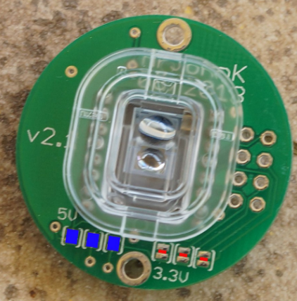
As a way to get real closed loop navigation the ADNS-9800 Laser Motion Sensor is being used to track the movement over the cable. This sensor is still to be integrated in the latest prototype, tests are being made to warranty that the cable is always visible to the sensor independently of the tension level.
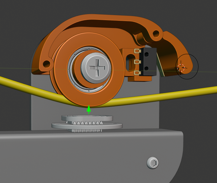
Optimal position of the laser sensor.
IMULink
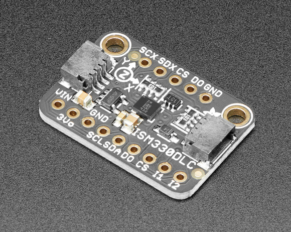
An Inertial measurement unit is used to give feedback to the microcontroller about balance and vibrations, acceleration and speed algorithms to take advantage of this data are still under development. The ISM330 Adafruit QWIIC breakout board is being used through I2C bus.
Compatible Adafruit library Arduino library
EndstopsLink
To detect collisions OMRON D3V-013-1C23 miniature switches are used as end stops on both sides of the cablebot. A 3d printed cover protects the electronic parts and triggers the switch when an obstacle is found. Cabling is routed through the structure to avoid any damage on the lines.
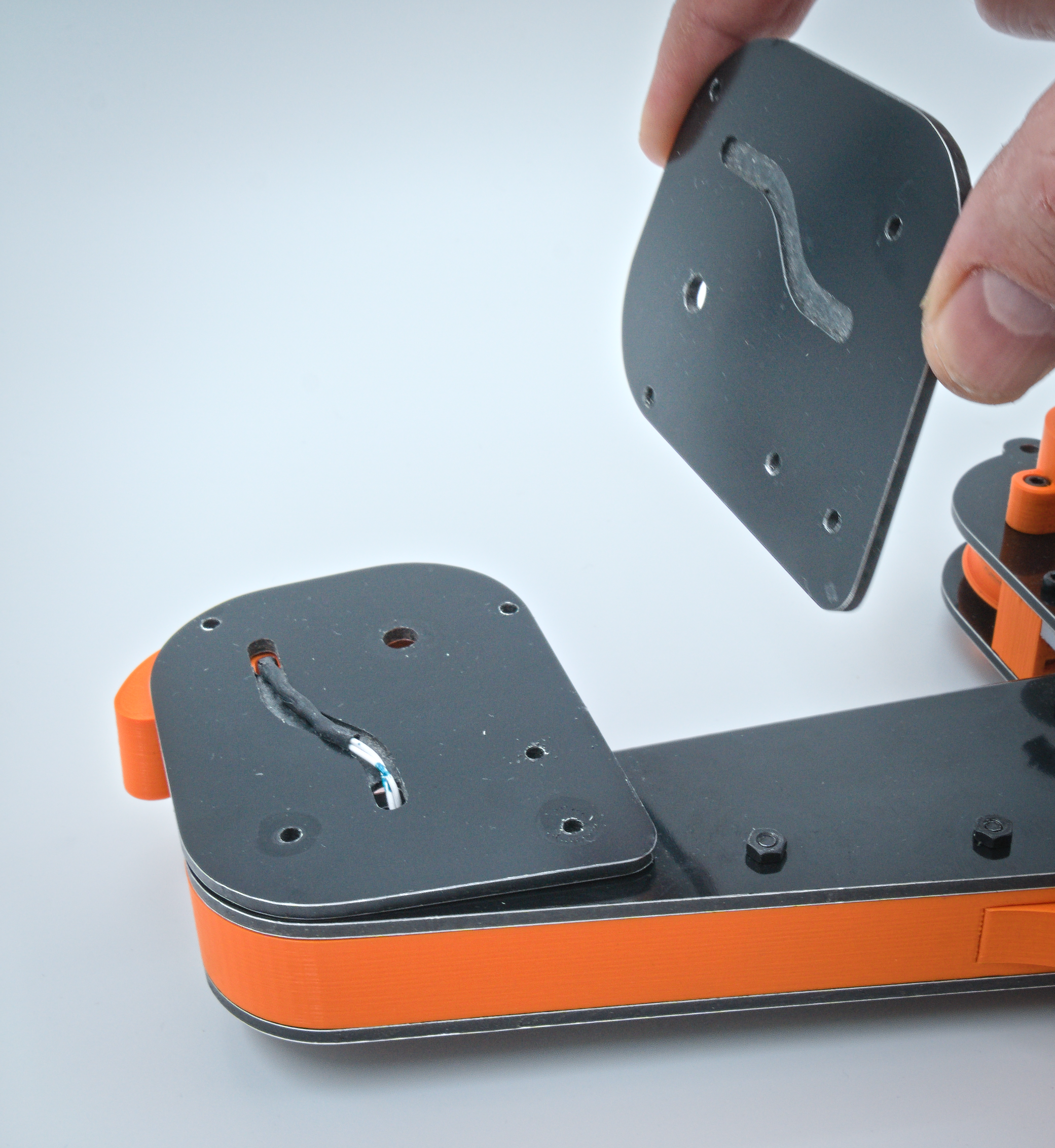
The cabling is routed trough machined channels between the aluminum sandwich sheets keeping it protected and organized.
Remote ControlLink
Any radio frequency remote control with at least one channel can be used with the CARM. We use one PWM channel to control the speed along the cable. A second PWM channel is already wired to be used in the future, for example to control camera orientation.
We have used HK-GT2B model with good results.
- 2.4GHz AFHDS signal operation
- 3CH operation
- 3.7v 800mAh Rechargeable li-ion transmitter battery
- RF Power: 20dBm (100mW) max
- Modulation: GFSK
- Sensitivity: 1024
- Transmitter Weight: 270g
- Receiver power: 4.5~6.5 VDC
Depending on the RF hardware sometimes adjusting the signal top/down limits with the remote potentiometers is not enough, this values can be adjusted on firmware changing the RC_CALIBRATION constant values for Min, Middle and Max values here.
To find out the values of your remote print to the console the value of the rcSpeed variable, somewhere in your loop() function and check the serial output while the trigger is at rest, top and bottom positions.
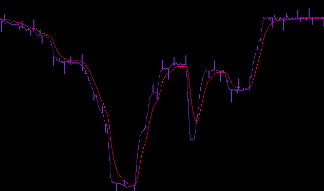
To minimize vibrations of the carrier module while operated with the RF remote control, the noise on the signal is cleaned, applying exponential smoothing to it.