Hardware DocumentationLink
This document describes the hardware, both the mechanical parts and the electronics, of the Romi Rover for weeding. This document is detailing the third version of the prototype.
The design files for the hardware can be found in a dedicated GitHub repository.
The main structureLink
The figure below gives an overview of the main components.
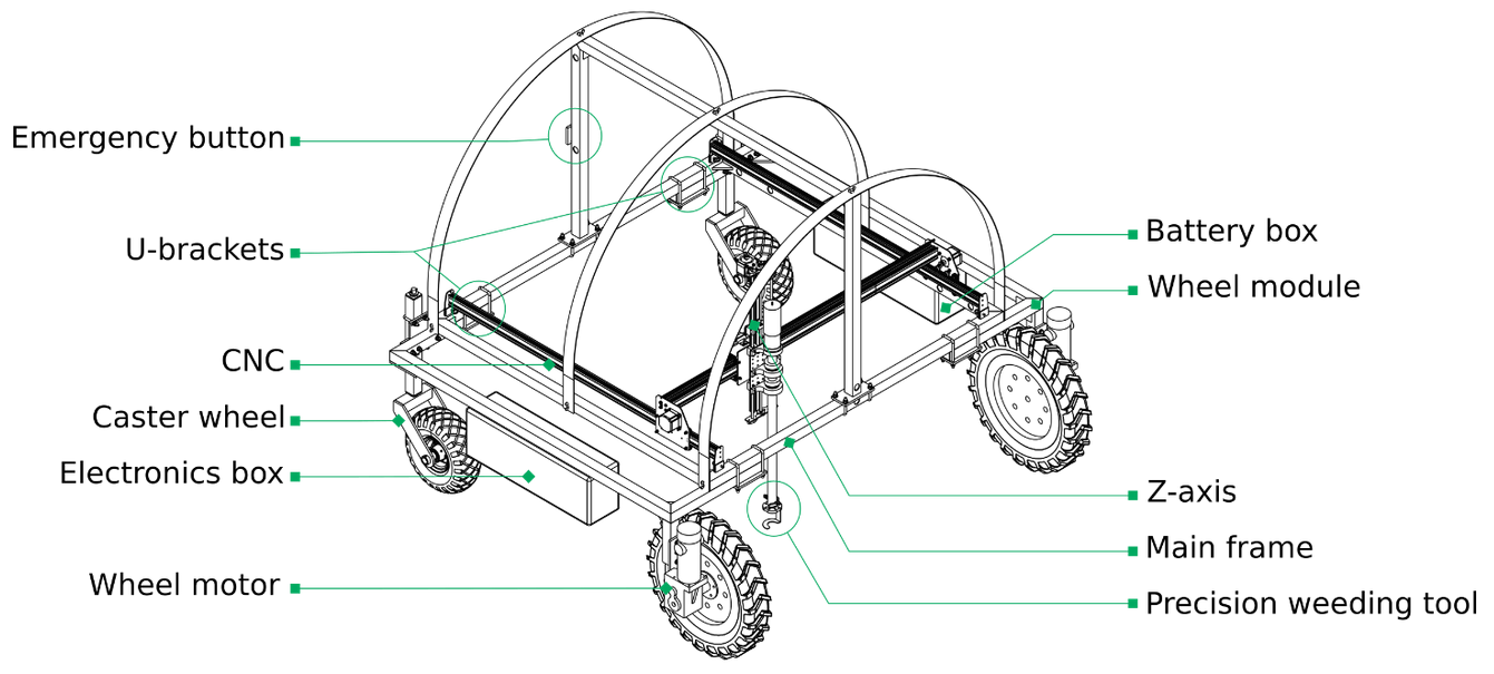
The documentation is split into two main parts: the rover and the weeding tool.
For the rover, you will find the detailed drawings of frame in the next section. The mechanical components that we use are listed in the follow-up section. Then, we discuss the electronics and wiring.
The weeding tool consists of a CNC, for which we use the 1000 mm XCarve. We replace the z-axis of the original CNC with a new arm adapted for the weeding task.
You can find the discussion of the software in a dedicated page of the rover documentation.
The roverLink
The frameLink
The drawings of the frame are available as PDF files. The current version is prototype V3:
| File | Description |
|---|---|
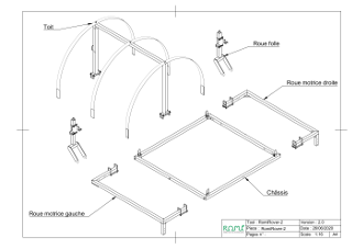 |
Overview of the components |
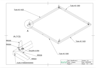 |
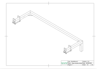
The main frame. (fr: Châssis) |
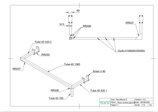 |
The left wheel module (fr: Roue motrice gauche) |
 |
The right wheel module. It is a mirror of the left wheel module. (fr: Roue motrice droite) |
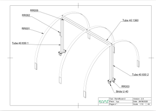 |
The arches for the rain and light cover. (fr: Toit) |
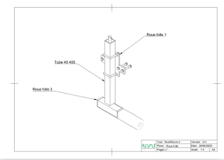 |
The caster wheel. (fr: Roue folle) |
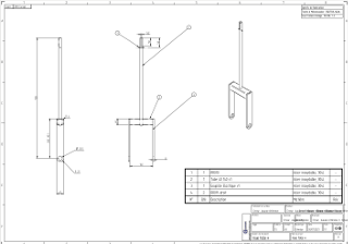 |
In it's latest version, the caster wheel now has a straight fork. This drawing updates and replaces the fork in the previous drawing. |
The mechanical componentsLink
The list of additional components to get the rover up on its feet are as follows. For the back wheels:
| File | Description |
|---|---|
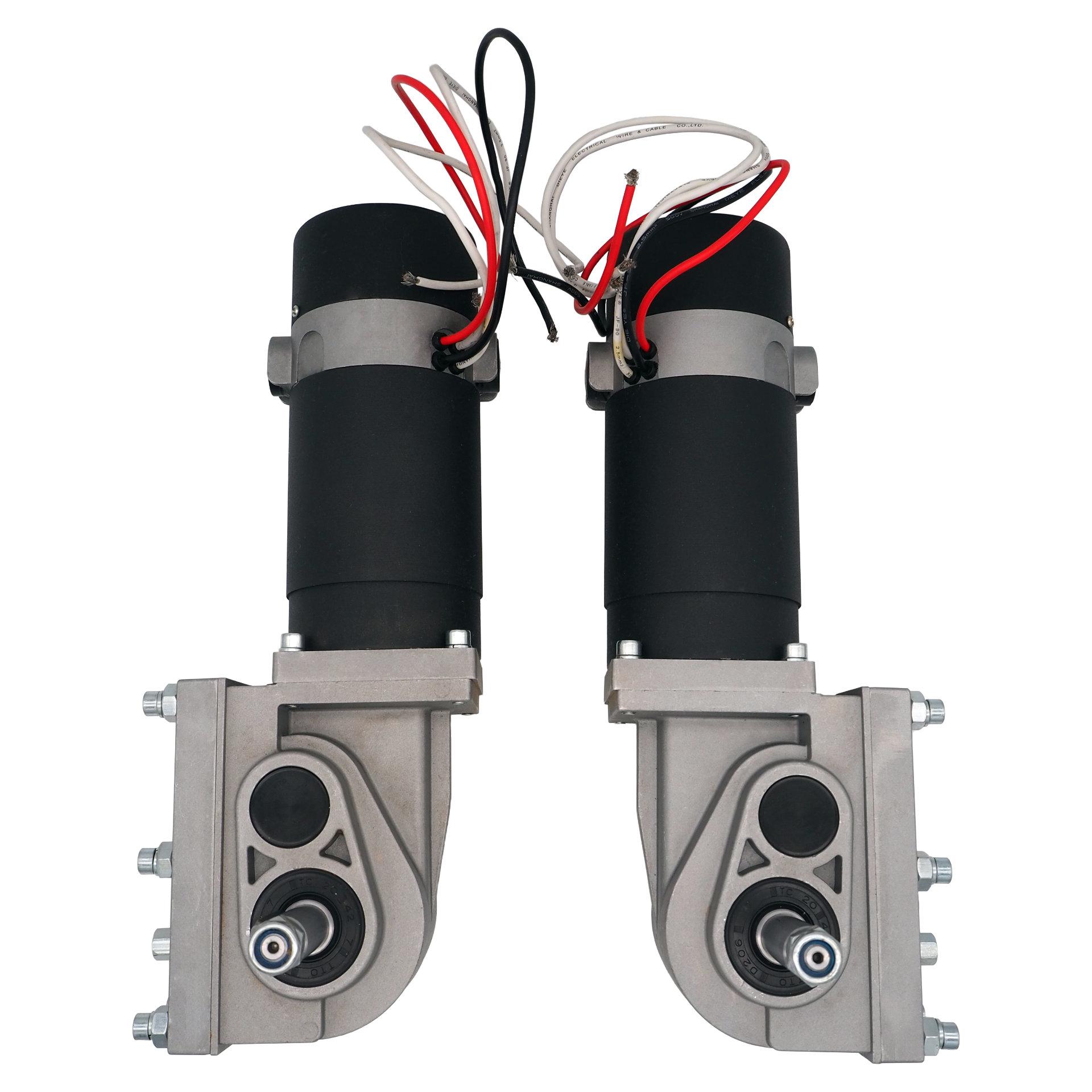 |
Brushed DC motors, 24 V, minimum 200 W We are using wheel chair motors for now. We bought a set at Superdroid Robots. You may find similar motors elsewhere, such as on Aliexpress. |
 |
Incremental encoders: The motors from Superdroid Robots can be purchased with encoders already added to them. If you want to buy them separately, we use the US Digital E2. |
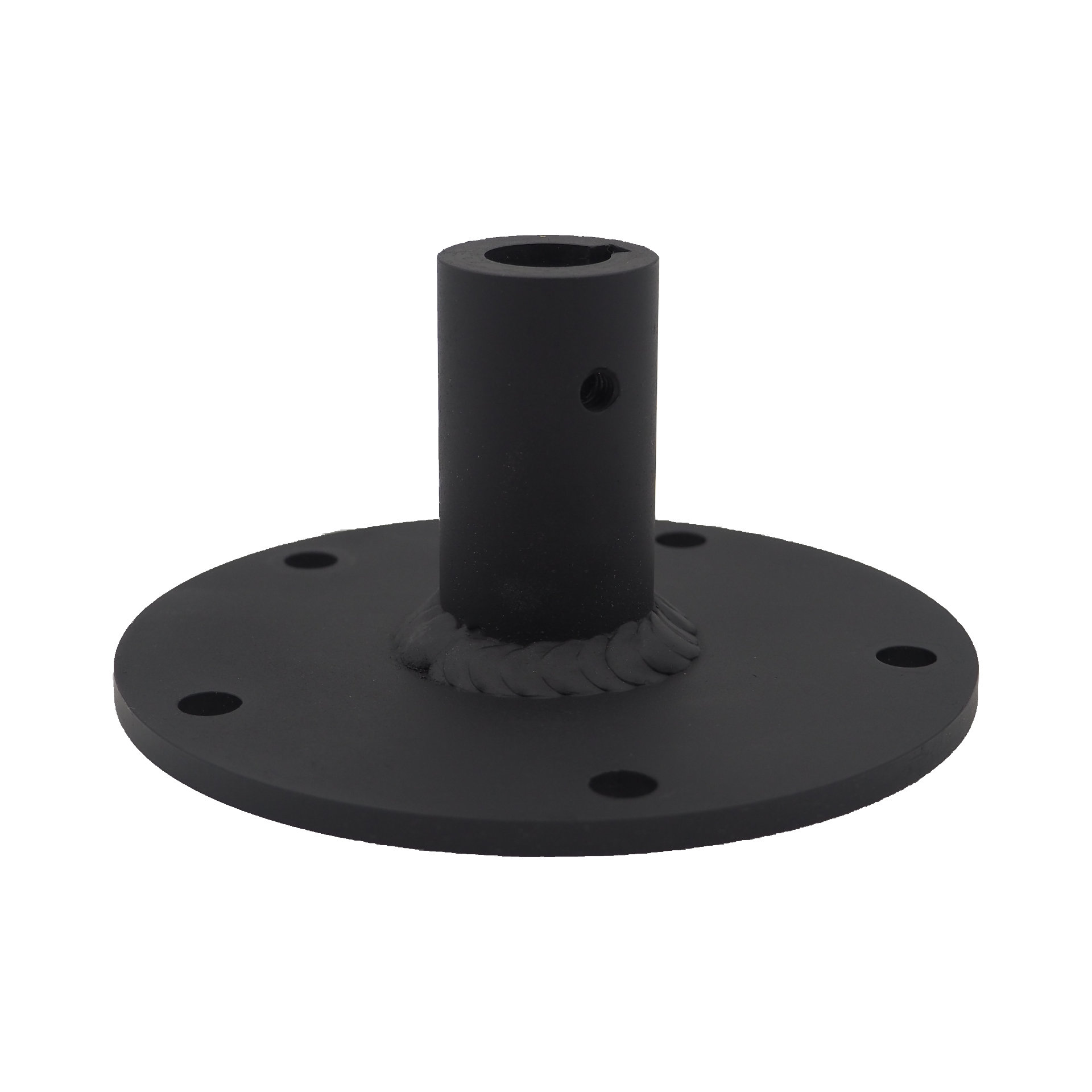 |
Wheel shaft: Still from Superdroid Robots we use the wheel shaft that is adapted to the motors. |
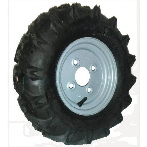 |
For the back wheels we use wheels with traction lugs for farming equipment with a total diameter of roughly 41 cm diameter or 49 cm. Browsing the catalogs of farming wheels can be confusing because of the different standards and naming conventions, and because the tire and rim are often sold separately. We are using these 4.00-10 tires or 4.00-8 tires. The "4" indicates the width of the tire in inch, and the 8 or 10 indicates the diameter of the wheel rim in inch. |
You'll notice that the our wheel rim has 4 holes while the wheel shaft has 5 holes... We ended up drilling new holes in the wheel shaft that aligned with those of the rim.
For the front wheels:
| File | Description |
|---|---|
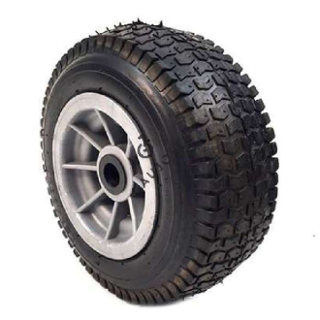 |
The front wheel |
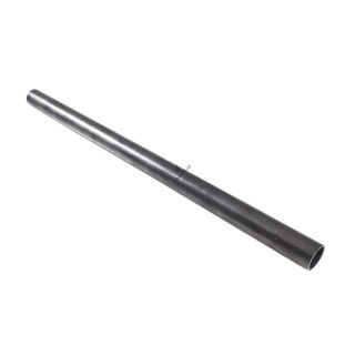 |
The 25 mm axis. |
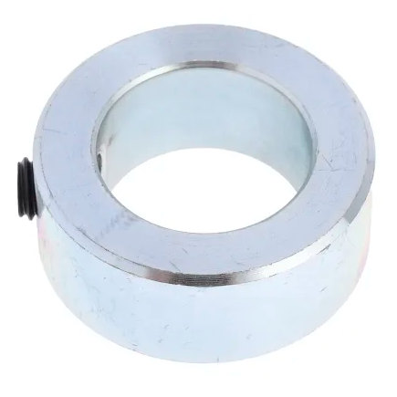 |
The adjusting rings. |
The housing of the battery and the electronics are currently built from wood :) This is because we haven't found a good way, yet, to build waterproof housing inexpensively. Made-to-measure housings are quite expensive. Professional housings with the right size tend to be even more expensive, or they have features such as ribbed walls that make them unsuited for our needs. We will solve this issue in the next version of the prototype.
| File | Description |
|---|---|
| Battery housing | 20mm plywood, outside dimensions: WxHxD (width x height x depth) |
| Electronics housing | 10mm plywood, outside dimensions: WxHxD (width x height x depth) |
The electronics and wiringLink
An overview of the wiring can be found in the following diagram. The diagram is quite large so you may want to open it in a separate window or download it and open it with Inkscape. Here's the GitHub link of this file.

The Meanwell DDR-30G-24 transformer converts the battery voltage level to a stable and clean 24V that powers the electronics. It is not powerfull enough to drive the motors (wheels, CNC, hoe) so these are draw there current directly from the battery.
The Controllino Mini is a Programmable Logic Controller that manages the power supply to the motors. It uses three inputs to decide whether power should be supplied or not to the motors: the emergency switch, the on/off button, and the status pin of the Raspberry Pi.
The Controllino does not provide the power directly to the motors. It uses the 24V relay from Finder to connect or disconnect the battery power. The power relay is designed to handle strong currents and has a protection against sparks and back-currents.
We also added a 24V USB hub. It provides four additional USB ports and reduces the power that would be drawn from the USB ports of the Raspberry Pi without it since the hub takes its power from the 24V line.
The brain of the rover is the Raspberry Pi 4. We added a HifiBerry shield so that the rover can output sound but also because it has a good 24V to 5V converter onboard. We designed a hat for the level shifter (needed to connect to the Controllino), the real-time clock (RTC), and the connector. You will find the details below.
The components inside the electronics housing are fixed on a 50 cm long, 35 mm DIN rail. We also use distribution blocks and rail mounts:
| File | Description |
|---|---|
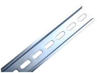 |
50 cm DIN rail. Example |
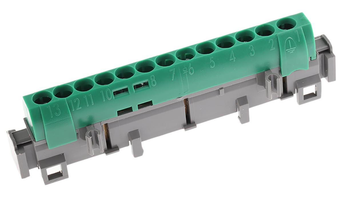 |
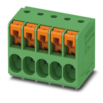
We also use distribution blocks that clips on the DIN rail. Example. These mounting carriers from Wago are also very handy for connecting low-power wires: Wago 222 Series and the their classic splicing connector. Although we have not used them, the terminal blocks by Phoenix Contact may be worth a try. |
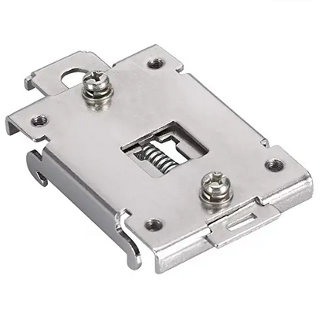 |
For the 3D printed housings that are clipsed on the DIN rail we use these "35mm Rail Mounting Bracket". |
A more detailed overview of the wiring is shown in the following diagram (TODO: must be updated). Again, you can download the diagram and open it in Inkscape or in a separate browser window, for a more detailed view.

There are two separate power circuits:
- Logic circuit: This circuits powers the embedded PC and other control circuits.
- Power circuit: This circuit drives all the motors. This is the circuit that is cut when the security switch (the big red button) is pressed.

The power circuits are controller by the Controllino according to the two start-up phases (the PC and the logic circuits start up first, then the motors are powered up).
| Component | Description |
|---|---|
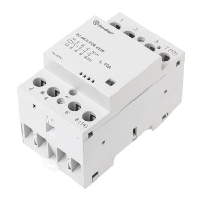 |
Non-Latching, protection against sparks and back-current (TODO: be more precise) RS Online |
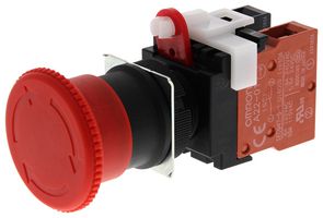 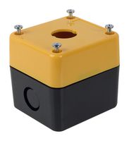 |
Farnell: button and housing |
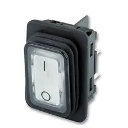 |
The on-off switch Farnell |
The displayLink
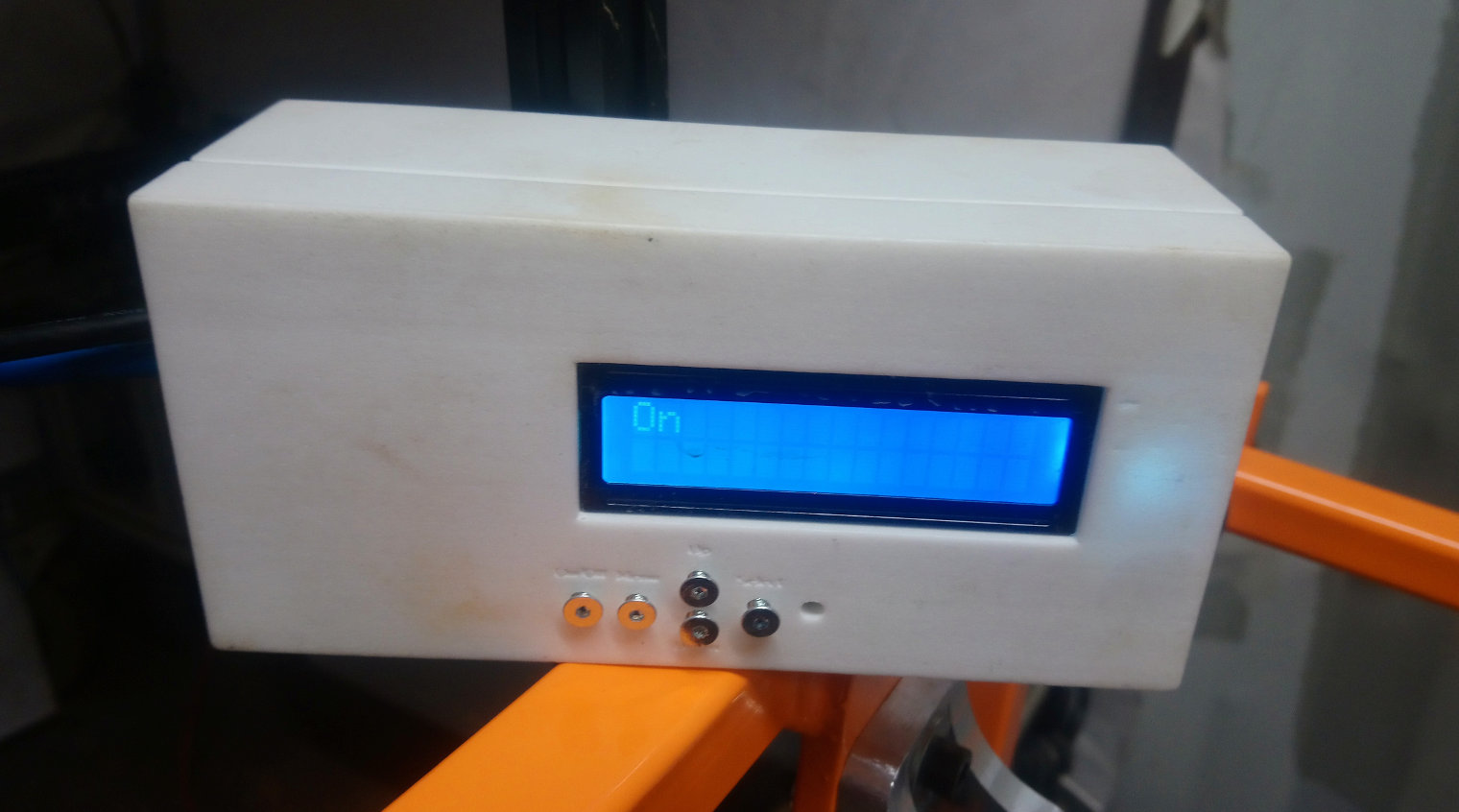
The display is used to show status information from the control software. It also allows you to list the menu of actions that are programmed on the rover. The display is connected to the Raspberry Pi over USB. The associated firmware for the Uno is CrystalDisplay.
| Component | Description |
|---|---|
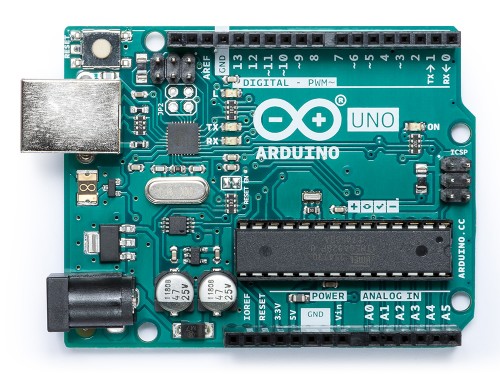 |
Arduino Uno |
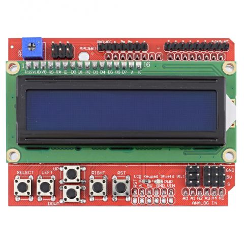 |
We use the following shield with LCD screen: GM Electronic. There are similar clones available online. |
The navigation moduleLink
The navigation uses a differential wheel drive, with two motorized wheels in the back and two swivel caster in the front. This makes the control fairly straight-forward and the components are easy to source.
The main components are shown below:

| Component | Specifications | Example |
|---|---|---|
|
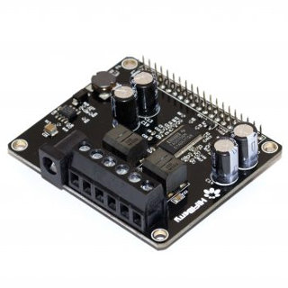
Arduino Uno | |
| Shield | The shield allows you to connect the wires securely. TODO: PCB design. |
The associated firmware for the Uno is MotorController.
TODO: 3D housing for motor controller
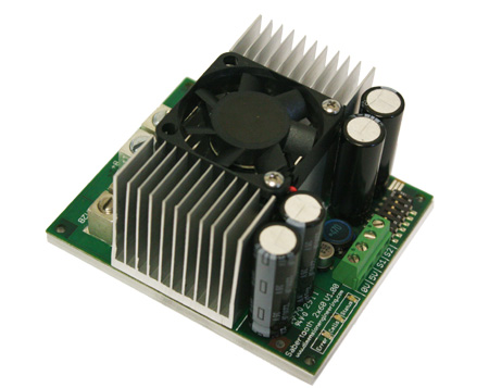
The motor controller connects to the motor driver. The driver implements a standard H-bridge to control to power supplied to the motors (both forward and backward rotation). We use the Sabertooth 2x60A. There are other motor drivers out there that can be used also. The power input should be 24V and there should be able to drive a lot of current current (> 15 A continuous, 40 A peak).
Two PWM control signals are used from the Arduino to the driver, similar to RC input: one for the left and right motor.
The wiring diagram

TODO: DIN support for Sabertooth.
The Raspberry PiLink
We wrapped the Raspberri Pi 4 in ints own housing, together with some additional components. First, we have put a HifiBerry Amp2 hat on it. The HifiBerry is a high-end audio amplifier and you can connect two analog audio speakers to it. This is maybe a little extravagant because this board does not come cheap and its usage is currently still limited. Audio feedback is planned for the future, though. Also, we use the HifiBerry as a power adapter because it converts the 24V to the 5V needed by the Raspberri Pi. All this we probably be re-evaluated in upcoming versions.
We also added a level-shifter, to communicate with the Controllino. We also added connector plugs and a ventilator to air the housing.
| Component | Link |
|---|---|
 |
HifiBerry Amp2 |
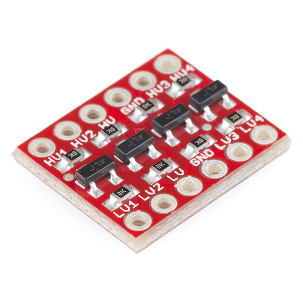 |
Level-shifter: Sparkfun |
 |
For the connectors, we use the following from Phoenix Contact: 1x 5 way, 1x 2 way, and 1x 4 way |
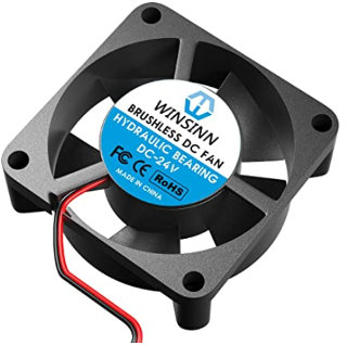 |
Ventilator 12/24V, 30 x 30 x 10 mm Amazon |
We designed a PCB board to put all pieces together (TODO: files) and a housing to protect it all (TODO: file).
The software of the rover is available in Github and has its own documentation.
The cameraLink
The camera uses the standard Raspberry Pi Zero 2 W together with the Raspberry Pi Camera V2. The software of the camera is part of the main repository and is also documented on the software page.
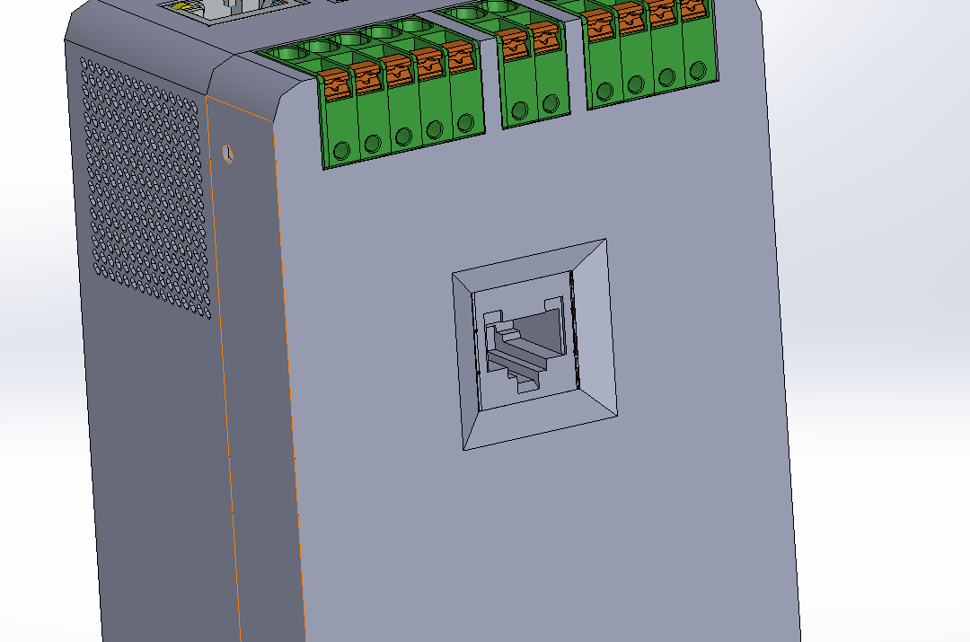
The camera is powered by a 24 V line (plus ground) directly from the Meanwell power adaptor. We designed a PCB board to support the MP1584EN-based 24V-to-5V DC-DC buck converter to power the Pi Zero and we also add a RJ45 connection plug. This
The 3D file of housing can be found here.
TODO: PCB file
The camera is up for a review because we want to switch to the Raspberry Pi HQ Camera.
The steeringLink
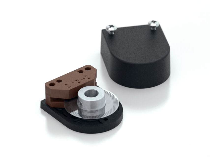
The steering of the front wheels is currently performed by two NEMA 23 stepper motors with a 1:77 gearbox. The stepper motors are controlled by two standard stepper controller and an Arduino Uno. We also use two absolute rotary encoders from Opkon to adjust for errors.
NOTE: at the time of writing, the steering controller has not been integrated into the electronics housing, yet.
The coupling of the stepper motors and of the encoder onto the wheel axis is still provisional. We use a coupler to join the wheel axis to the motor. To connect the encoder to the axis, we use a GT2 belt and two 3D printed pulleys, one for the wheel axes and one for the encoder.
It is all held together using 3D printed components and two laser-cut aluminium plates. It look roughly like this:
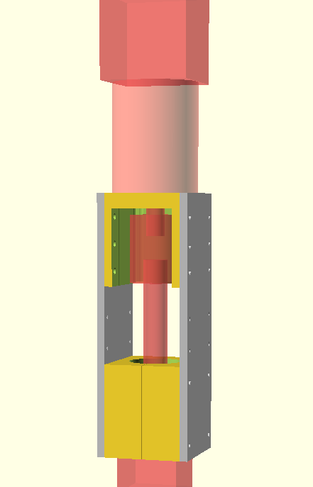
The 3D files files are available at romi-rover-design/steering.
TODO: link coupler, length GT2 belt
The weeding toolLink
The CNCLink
A CNC is adapted for use in the rover. We are using the 1000 mm sized version of the X-Carve. We replaced the spindle that is normally used to carve wooden pieces, with a rotating weeding hoe.
The newer X-Carve uses a custom design board for the control. However, we prefer using the older solution that combines an Arduino Uno with a gShield because it is smaller and more generic. It is possible to use other stepper drivers. The drivers must use the standard STEP/DIR control signals. The associated firmware for the Uno is Oquam.
| Component | Specifications | Example |
|---|---|---|
|
Arduino Uno | |
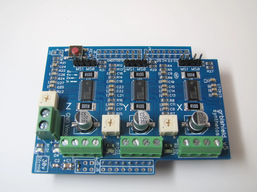 |
Stepper drivers (3 steppers): gShield |
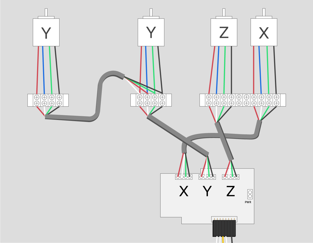
For the wiring, you can still have a look at XCarve's older documentation on how to wire the controller boards:
- http://x-carve-instructions.inventables.com/xcarve2015/step10/
- http://x-carve-instructions.inventables.com/xcarve2015/step14/
Notable, the following two diagrams are of interest:
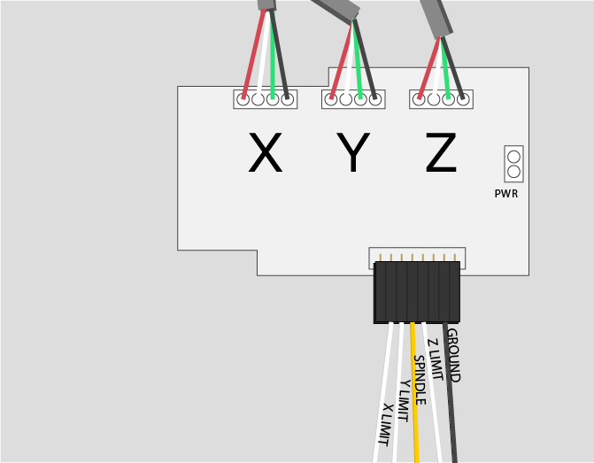
The yellow wire marked "spindle" in the image above is used to turn the weeding hoe on or off, as shown in the figure below (see also the figure in the section on the power circuit).

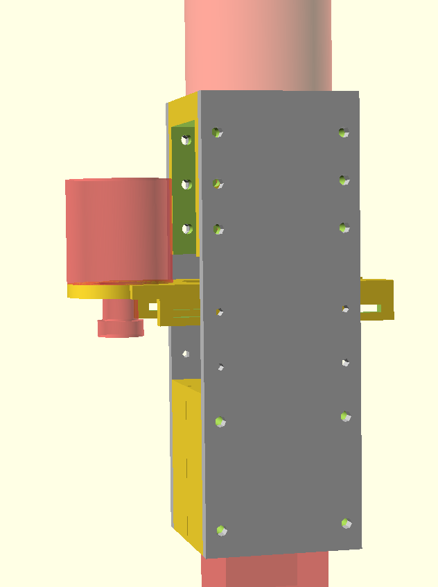
The Z-axisLink
We replaced the default z-axis of the CNC with a longer and stronger axis to carry the weeding tool.
The new axis uses standard mechanical elements together with laser-cut plates and 3D printed components. The 2D and 3D designas are available here here. You will find the list of additional components below.
The gShield has a pin to turn the spindle on/off. This pin actuates the power relay shown in the list below to start/stop the motor.
| Component | Quantity | Specifications |
|---|---|---|
| Flange Bearing 8mm | 2 | Motedis KFL08 |
| Trapezoidal threaded TR 8x1,5 | 630 mm | Motedis |
| GT2 pulley 20 teeth 8mm bore | 1 | Motedis |
| Shaft | 2 x 600 mm | Motedis |
| Shaft supports | 4 | Motedis |
| Anti-backlash nut | 1 | Motedis |
| Linear plain bearing | 4 | Motedis |
| Linear bearings | 4 | Motedis |
| Power relay | 1 | Sparkfun |
The weeding headLink
We use a rather simple design for the weeding head. The support can be produced using a 3D printer and the four aluminium blades produced using a professional laser-cutting service. We have drawn a couple of alternative designs but these have not been tested, yet.